Introduction
Navigation is the ability of a mobile robot to determine its position in the environment where it is located (localization), and to plan and execute the path to a target location. It enables autonomous avoiding both static and dynamic obstacles. For navigation to work, it is very important to have a map of the environment. Yesterday (Day 2, Simulation (Gazebo, move_base)) when we demonstrated how navigation works in ROS using standard move_base node, we used a mobile robot simulation where an environment map has already been built in advance. It's also very likely for a mobile robot to start operating in an environment for which it has not yet been given a map in advance, so in such a case, it must first build one. The process of creating a map is called mapping.
In the following, some basics of mapping will be briefly presented, followed by a practical task where you will build a map of the environment in a mobile robot simulation.
AMCL/gmapping
AMCL and gmapping (or some other SLAM algorithm) are important parts for mapping process. AMCL (Adaptive Monte Carlo Localization) is a probalistic localization system for a robot moving in 2D (Source: ROS amcl). In ROS, amcl is a node which uses a map, laser scans, and transform messages, and outputs pose estimates.
Gmapping is an implementation of a specific SLAM (Simultaneous Localization And Mapping) algorithm. Gmapping is an algorithm that is already implemented in ROS, meaning that someone has already implemented this algorithm in ROS before us, so we don't need to program it, we just need to run the right node or launch file in the terminal.
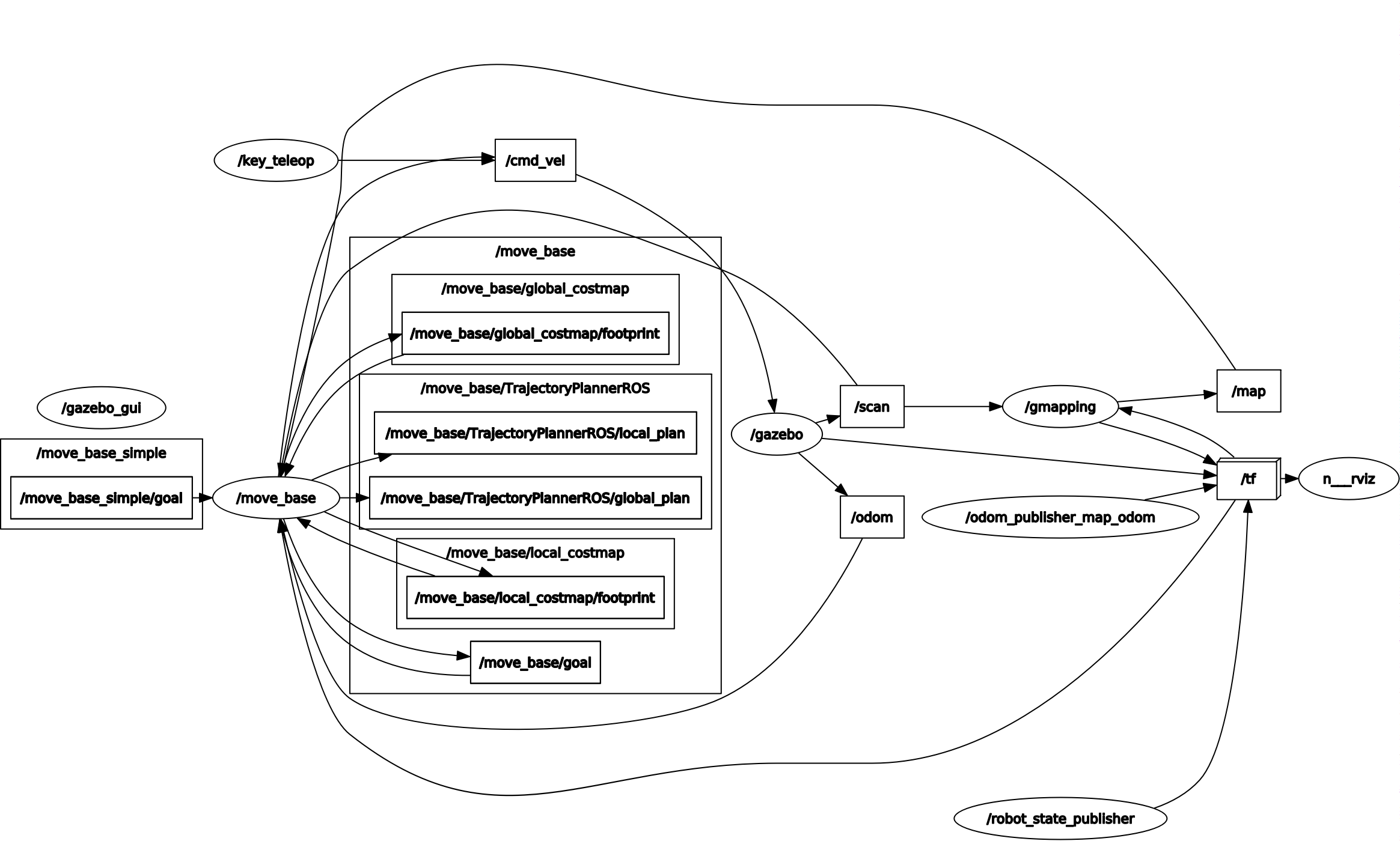
The gmapping package contains the ROS node slam_gmapping, which builds a 2D map, using data on laser sensor measurements and the data on the position of the mobile robot. The node slam_gmapping (in our simulation this node is named gmapping) is subscribed to the topics /scan and /tf, in order to obtain the necessary data to build the map. This node reads data from the laser and transformations and then creates OGM (Occupancy Grid Map) based on that data. The map that is being created is being published on the topic /map throughout the mapping process. Topic /map uses a message of type nav_msgs/OccupancyGrid. In OGM, the occupancy is represented by the integer value in the range from 0 to 100. A value of 0 means completely unoccupied and 100 means fully occupied (e.g., wall), and a special value is -1, which means an unknown area. (Source: Mapping & Create a map from zero)
SLAM (Gazebo)
This section describes how to build an environment map in a mobile robot simulation. Just follow the individual steps below.
If not yet, create a new package rosbot_mapping inside workspace rosbot_ros:
cd .../rosbot_ros/src

catkin_create_pkg rosbot_mapping std_msgs roscpp
Step 1. In the package rosbot_mapping, in folder .../rosbot_mapping/launch create a new file and name it simulation_mapping.launch.
Step 2. Open sumulation_mapping.launch file and paste the code below in it:
<?xml version="1.0" encoding="UTF-8"?>
<launch>

    <!-- GAZEBO -->
    <include file="$(find rosbot_simulation)/launch/gazebo.launch">
    </include>

    <node pkg="teleop_twist_keyboard" type="teleop_twist_keyboard.py" name="key_teleop" output="screen"/>

    <!-- run gmapping to map the floor -->
    <node pkg="gmapping" type="slam_gmapping" name="gmapping" args="scan:=scan _base_frame:=/base_link _odom_frame:=/odom
    _map_update_interval:=1
    _maxUrange:=2.0
    _iterations:=5
    _minimumScore:=600.0
    _linearUpdate:=0.2
    _angularUpdate:=0.1
    _particles:=30
    _delta:=0.05
    _llsamplerange:=0.01
    _maxRange:=2.0"
    output="screen"/>

    <node name="rviz" pkg="rviz" type="rviz"/>

</launch>
Step 3. Run the mapping simulation:
cd .../rosbot_ros/

catkin_make

source devel/setup.bash

roslaunch rosbot_mapping simulation_mapping.launch
Step 4. In the RViz, add objects needed for the mapping process (mobile robot position, laser scan, map).
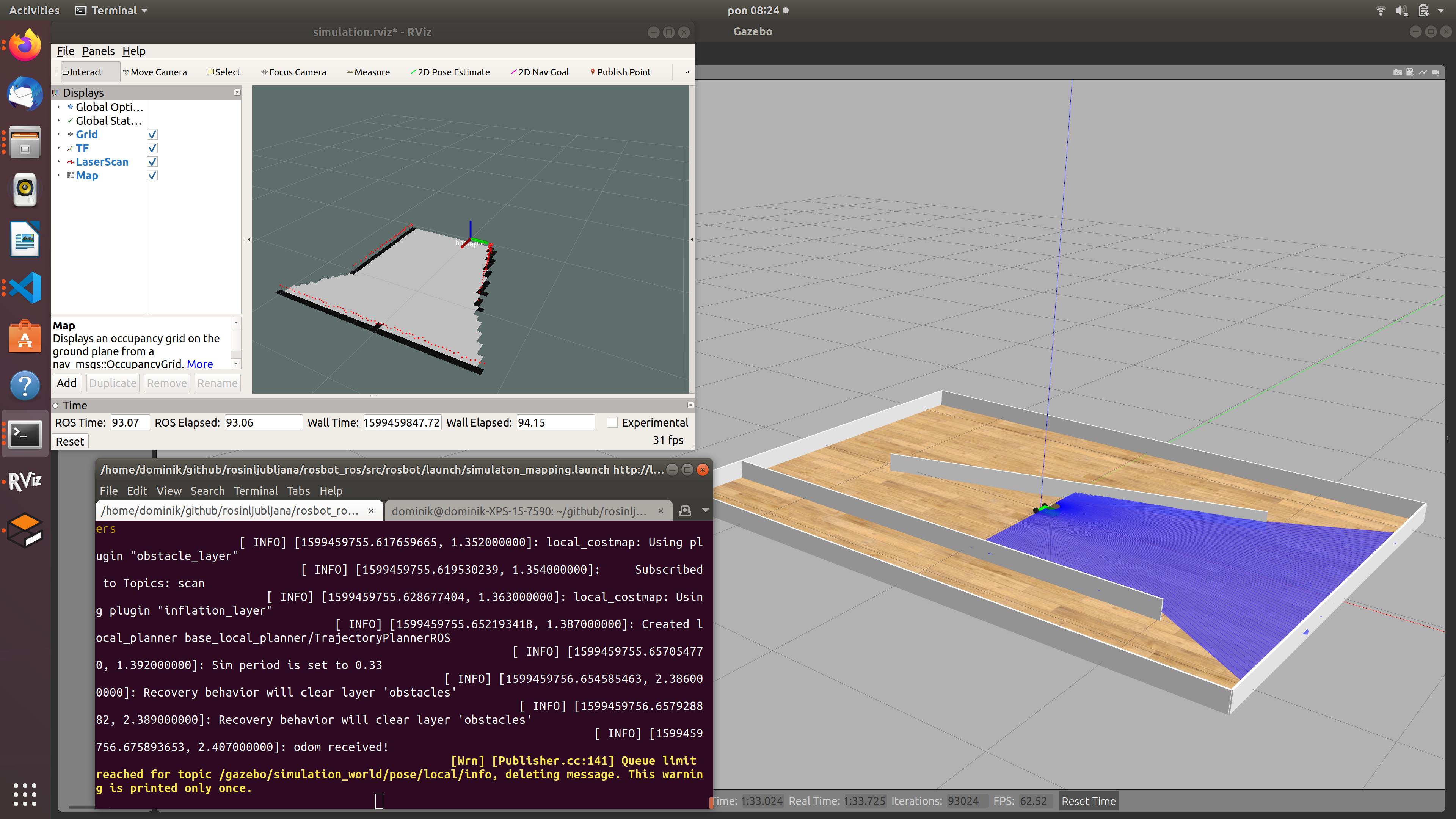
Step 5. Using the PC's keyboard, drive the mobile robot around in such a way that the entire map of the environment in which the mobile robot operates is built (mapping.launch already includes a node teleop_twist_keyboard). If you will use teleop_twist_keyboard node, we recommend you to decrease linear speed by pressing (multiple times) the key "x" on a keyboard. Alternatively, you can use mouse_teleop node. But because mouse_teleop node isn't yet included in the .launch file, you must add it by yourself, or run the mouse_teleop node in the second tedminal. Either way, drive the mobile robot around for as long as it takes to build a full map. The current status of the map can be monitored in RViz.
Step 6. Save the built map by executing the command below in another terminal:
rosrun map_server map_saver -f my_map_simulation
The map will be saved in a workspace folder .../rosbot_ros.
Using a newly created map
Run the simulation of the mobile robot, but this time the mobile robot should use the map we have just created (named my_map_simulation) for navigation.
Help: The my_map_simulation.pgm and my_map_simulation.yaml files created with the mapping process must be copied in to the folder …/rosbot_simulation/map/, and in the simulation.launch file, the map file name must be changed to my_map_simulation.yaml (instead of map_simulation.yaml), and then in the usual way run the simulation with the command:
roslaunch rosbot_simulation simulation.launch
Additional task: In Gazebo, add an obstacle (e.g., a block or a cylinder) and test whether the mobile robot can detect and avoid this obstacle, even though this obstacle is not included in the map.