Introduction
In this section, we will learn how a mobile robot simulation can be built in ROS.
The main tool for making simulations in ROS is a open-source software tool called Gazebo. Gazebo is a simulator for robotics. It enables accurate and efficient simulations of robots in complex indoor and outdoor environments. ROS is integrated with stand-alone Gazebo with a set of ROS packages named gazebo_ros_pkgs. More information about the Gazebo in ROS can be found on the links below:
In the assignments below, you will first learn how to build a mobile robot simulation in ROS step by step and how to launch that simulation. At the end of this section, you will also learn a more advanced way of controlling a mobile robot via standard ROS node called move_base.
Create a mobile robot simulation
Here is a step-by-step description of how to build a mobile robot simulation. Individual parts of the simulation program code are also given. Just follow the descriptions and steps below.
URDF
URDF is an XML file format used in ROS to describe all elements of a robot. The URDF file describes the kinematics and physical properties of the robot. You can find more information about the URDF file on the link below:
URDF description of our mobile robot
Below is a URDF description of our mobile robot (two files: robot.xacro and parameters.xacro).
robot.xacro file:
<?xml version="1.0"?>
<robot name="rosbot"
    xmlns:xacro="http://www.ros.org/wiki/xacro">
    <!-- INCLUDES -->
    <xacro:include filename="$(find rosbot_simulation)/urdf/parameters.xacro" />
    <!-- BASE LINK -->
    <link name="base_link">
        <material name="orange"/>
        <!-- pose and inertial -->
        <pose>0 0 0 0 0 0</pose>
        <inertial>
            <origin rpy="0 0 0" xyz="${base_size_x/2} 0 0"/>
            <mass value="${base_mass}"/>
            <xacro:box_inertia mass="${base_mass}" x="${base_size_x}" y="${base_size_y}" z="${base_size_z}"/>
        </inertial>
        <!-- body -->
        <collision name="base_front_collision">
            <origin rpy="0 0 0" xyz="${base_size_x/2} 0 0"/>
            <geometry>
                <box size="${base_size_x} ${base_size_y} ${base_size_z}"/>
            </geometry>
        </collision>
        <visual>
            <origin rpy="0 0 0" xyz="${base_size_x/2} 0 0"/>
            <geometry>
                <box size="${base_size_x} ${base_size_y} ${base_size_z}"/>
            </geometry>
            <material name="green"/>
        </visual>
        <!-- caster front -->
        <collision name="caster_front_collision">
            <origin rpy=" 0 0 0" xyz="${base_size_x} 0 ${-wheel_radius/2}"/>
            <geometry>
                <sphere radius="${wheel_radius/2}"/>
            </geometry>
            <contact_coefficients/>
            <surface>
                <contact>
                    <ode>
                        <kp>${caster_kp}</kp>
                        <kd>${caster_kd}</kd>
                    </ode>
                </contact>
                <friction>
                    <ode>
                        <mu>${caster_mu}</mu>
                        <mu2>${caster_mu2}</mu2>
                        <slip1>${caster_slip1}</slip1>
                        <slip2>${caster_slip2}</slip2>
                    </ode>
                </friction>
            </surface>
        </collision>
        <visual>
            <origin rpy=" 0 0 0" xyz="${base_size_x} 0 ${-wheel_radius/2}"/>
            <geometry>
                <sphere radius="${wheel_radius/2}"/>
            </geometry>
            <material name="gray"/>
        </visual>
    </link>
    <!-- LEFT WHEEL LINK -->
    <link name="left_wheel_link">
        <inertial>
            <mass value="${wheel_mass}"/>
            <origin rpy="0 1.5707 1.5707" xyz="0 0 0"/>
            <xacro:cylinder_inertia mass="${wheel_mass}" r="${wheel_radius}" l="${wheel_width}"/>
        </inertial>
        <collision name="left_wheel_collision">
            <origin rpy="0 1.5707 1.5707" xyz="0 0 0"/>
            <geometry>
                <cylinder radius="${wheel_radius}" length="${wheel_width}"/>
            </geometry>
            <surface>
                <contact>
                    <ode>
                        <kp>${wheel_kp}</kp>
                        <kd>${wheel_kd}</kd>
                    </ode>
                </contact>
                <friction>
                    <ode>
                        <mu>${wheel_mu}</mu>
                        <mu2>${wheel_mu2}</mu2>
                        <slip1>${wheel_slip1}</slip1>
                        <slip2>${wheel_slip2}</slip2>
                    </ode>
                </friction>
            </surface>
        </collision>
        <visual>
            <origin rpy="0 1.5707 1.5707" xyz="0 0 0"/>
            <geometry>
                <cylinder radius="${wheel_radius}" length="${wheel_width}"/>
            </geometry>
            <material name="gray"/>
        </visual>
    </link>
    <!-- LEFT WHEEL JOINT -->
    <joint name="left_motor" type="continuous">
        <origin rpy="0 0 0" xyz="0.0 ${base_size_y/2+wheel_width/2} 0.0"/>
        <child link="left_wheel_link"/>
        <parent link="base_link"/>
        <axis rpy="0 0 0" xyz="0 1 0"/>
        <dynamics damping="${motor_damping}" friction="${motor_friction}"/>
    </joint>
    <!-- RIGHT WHEEL LINK -->
    <link name="right_wheel_link">
        <inertial>
            <mass value="${wheel_mass}"/>
            <origin rpy="0 1.5707 1.5707" xyz="0 0 0"/>
            <xacro:cylinder_inertia mass="${wheel_mass}" r="${wheel_radius}" l="${wheel_width}"/>
        </inertial>
        <collision name="right_wheel_collision">
            <origin rpy="0 1.5707 1.5707" xyz="0 0 0"/>
            <geometry>
                <cylinder radius="${wheel_radius}" length="${wheel_width}"/>
            </geometry>
            <surface>
                <contact>
                    <ode>
                        <kp>${wheel_kp}</kp>
                        <kd>${wheel_kd}</kd>
                    </ode>
                </contact>
                <friction>
                    <ode>
                        <mu>${wheel_mu}</mu>
                        <mu2>${wheel_mu2}</mu2>
                        <slip1>${wheel_slip1}</slip1>
                        <slip2>${wheel_slip2}</slip2>
                    </ode>
                </friction>
            </surface>
        </collision>
        <visual>
            <origin rpy="0 1.5707 1.5707" xyz="0 0 0"/>
            <geometry>
                <cylinder radius="${wheel_radius}" length="${wheel_width}"/>
            </geometry>
            <material name="gray"/>
        </visual>
    </link>
    <!-- RIGHT WHEEL JOINT -->
    <joint name="right_motor" type="continuous">
        <origin rpy="0 0 0" xyz="0 ${-base_size_y/2-wheel_width/2} 0"/>
        <child link="right_wheel_link"/>
        <parent link="base_link"/>
        <axis rpy="0 0 0" xyz="0 1 0"/>
        <dynamics damping="${motor_damping}" friction="${motor_friction}"/>
    </joint>
    <!-- TRANSMISSIONS -->
    <transmission name="left_motor_transmission">
        <type>transmission_interface/SimpleTransmission</type>
        <joint name="left_motor">
            <hardwareInterface>hardware_interface/EffortJointInterface</hardwareInterface>
        </joint>
        <actuator name="left_motor">
            <hardwareInterface>EffortJointInterface</hardwareInterface>
            <mechanicalReduction>1</mechanicalReduction>
        </actuator>
    </transmission>
    <transmission name="right_motor_transmission">
        <type>transmission_interface/SimpleTransmission</type>
        <joint name="right_motor">
            <hardwareInterface>hardware_interface/EffortJointInterface</hardwareInterface>
        </joint>
        <actuator name="right_motor">
            <hardwareInterface>EffortJointInterface</hardwareInterface>
            <mechanicalReduction>1</mechanicalReduction>
        </actuator>
    </transmission>
    <!-- GAZEBO CONTROL -->
    <gazebo>
        <plugin name="differential_drive_controller" filename="libgazebo_ros_diff_drive.so">
            <rosDebugLevel>Debug</rosDebugLevel>
            <publishWheelTF>false</publishWheelTF>
            <robotNamespace>/</robotNamespace>
            <publishTf>1</publishTf>
            <publishWheelJointState>false</publishWheelJointState>
            <alwaysOn>true</alwaysOn>
            <updateRate>100.0</updateRate>
            <leftJoint>left_motor</leftJoint>
            <rightJoint>right_motor</rightJoint>
            <wheelSeparation>${base_size_y+wheel_width}</wheelSeparation>
            <wheelDiameter>${2*wheel_radius}</wheelDiameter>
            <broadcastTF>1</broadcastTF>
            <wheelTorque>0.1</wheelTorque>
            <wheelAcceleration>10</wheelAcceleration>
            <commandTopic>cmd_vel</commandTopic>
            <odometryFrame>odom</odometryFrame>
            <odometryTopic>odom</odometryTopic>
            <pose_covariance_diagonal>[1.0, 1.0, 0.0, 0.0, 0.0, 1.0]</pose_covariance_diagonal>
            <twist_covariance_diagonal>[0.01, 0.0, 0.0, 0.0, 0.0, 0.1]</twist_covariance_diagonal>
            <gaussianNoise>0.05</gaussianNoise>
            <robotBaseFrame>base_link</robotBaseFrame>
            <legacyMode>false</legacyMode>
            <publishOdomTF>true</publishOdomTF>
            <odometrySource>world</odometrySource>
        </plugin>
    </gazebo>
    <!-- GAZEBO LIDAR -->
    <link name="lidar_link">
        <visual>
            <origin xyz="0 0 0" rpy="0 0 0"/>
            <geometry>
                <box size="0.01 0.01 0.01"/>
            </geometry>
        </visual>
    </link>
    <joint name="laser_joint" type="fixed">
        <axis xyz="0 1 0" />
        <origin xyz="0.054 0.0 0.030" rpy="0 0 0"/>
        <parent link="base_link"/>
        <child link="lidar_link"/>
    </joint>
    <gazebo reference="lidar_link">
        <sensor type="ray" name="head_hokuyo_sensor">
            <pose>0 0 0 0 0 0</pose>
            <visualize>true</visualize>
            <!--  <update_rate>1</update_rate>  -->
            <update_rate>10</update_rate>
            <ray>
                <scan>
                    <horizontal>
                        <samples>180</samples>
                        <resolution>1</resolution>
                        <min_angle>-1.5717</min_angle>
                        <max_angle>1.5717</max_angle>
                    </horizontal>
                </scan>
                <range>
                    <min>0.05</min>
                    <!--  <max>0.55</max>  -->
                    <max>2.0</max>
                    <resolution>0.001</resolution>
                </range>
                <noise>
                    <type>gaussian</type>
                    <mean>0.0</mean>
                    <stddev>0.01</stddev>
                </noise>
            </ray>
            <plugin name="gazebo_ros_head_hokuyo_controller" filename="libgazebo_ros_laser.so">
                <topicName>scan</topicName>
                <frameName>lidar_link</frameName>
            </plugin>
        </sensor>
    </gazebo>
    <!-- GAZEBO IMU -->
    <link name="imu_link">
        <inertial>
            <mass value="0.001" />
            <origin xyz="0 0 0" />
            <inertia ixx="0.0" ixy="0.0" ixz="0.0" iyy="0.0" iyz="0.0" izz="0.0" />
        </inertial>
        <visual>
            <origin xyz="0 0 0" rpy="0 0 0" />
            <geometry>
                <box size = "0.005 0.005 0.005"/>
            </geometry>
        </visual>
        <collision>
            <geometry>
                <box size = "0.005 0.005 0.005"/>
            </geometry>
        </collision>
    </link>

    <joint name="imu_joint" type="fixed">
        <axis xyz="0 0 0"/>
        <origin xyz="0.080 0 0.01" rpy="0 0 0" />
        <parent link="base_link"/>
        <child link="imu_link" />
    </joint>

    <gazebo>
        <plugin name="imu_plugin" filename="libgazebo_ros_imu.so">
            <alwaysOn>true</alwaysOn>
            <bodyName>imu_link</bodyName>
            <frameName>base_link</frameName>
            <topicName>imu</topicName>
            <serviceName>imu_service</serviceName>
            <gaussianNoise>0.01</gaussianNoise>
            <updateRate>100.0</updateRate>
        </plugin>
    </gazebo>
    <gazebo reference="base_link">
        <material>Gazebo/Green</material>
    </gazebo>
    <gazebo reference="left_wheel_link">
        <material>Gazebo/DarkGrey</material>
    </gazebo>
    <gazebo reference="right_wheel_link">
        <material>Gazebo/DarkGrey</material>
    </gazebo>
</robot>
parameters.xacro file:
<?xml version="1.0"?>
<robot name="triglav"
    xmlns:xacro="http://www.ros.org/wiki/xacro">
    <!-- CYLINDER INERTIA -->
    <xacro:macro name="cylinder_inertia" params="mass r l">
        <inertia ixx="${mass*(3*r*r+l*l)/12}" ixy = "0" ixz = "0" iyy="${mass*(3*r*r+l*l)/12}" iyz = "0" izz="${mass*(r*r)/2}" />
    </xacro:macro>
    <!-- BOX INERTIA -->
    <xacro:macro name="box_inertia" params="mass x y z">
        <inertia ixx="${mass*(y*y+z*z)/12}" ixy = "0" ixz = "0" iyy="${mass*(x*x+z*z)/12}" iyz = "0" izz="${mass*(x*x+y*y)/12}" />
    </xacro:macro>
    <!-- BASE INERTIA -->
    <xacro:property name="base_mass" value="0.150" />
    <xacro:property name="base_size_x" value="0.10" />
    <xacro:property name="base_size_y" value="0.08" />
    <xacro:property name="base_size_z" value="0.01" />
    <!-- CASTER COLLISION -->
    <xacro:property name="caster_kp" value="10000000" />
    <xacro:property name="caster_kd" value="1.0" />
    <xacro:property name="caster_mu" value="0.0" />
    <xacro:property name="caster_mu2" value="0.0" />
    <xacro:property name="caster_slip1" value="1.0" />
    <xacro:property name="caster_slip2" value="1.0" />
    <!-- WHEEL INERTIA -->
    <xacro:property name="wheel_mass" value="0.100" />
    <xacro:property name="wheel_radius" value="0.016" />
    <xacro:property name="wheel_width" value="0.006" />
    <!-- WHEEL COLLISION -->
    <xacro:property name="wheel_kp" value="10000000" />
    <xacro:property name="wheel_kd" value="1.0" />
    <xacro:property name="wheel_mu" value="1.0" />
    <xacro:property name="wheel_mu2" value="1.0" />
    <xacro:property name="wheel_slip1" value="0.0" />
    <xacro:property name="wheel_slip2" value="0.0" />
    <!-- WHEEL JOINT -->
    <xacro:property name="motor_damping" value="0.000" />
    <xacro:property name="motor_friction" value="0.00000" />

    <material name="gray">
        <color rgba="0.2 0.2 0.2 1"/>
    </material>

    <material name="green">
        <color rgba="0.2 0.8 0.2 1"/>
    </material>
</robot>
If not yet, create a new package rosbot_simulation inside workospace rosbot_ros:
cd .../rosbot_ros/src

catkin_create_pkg rosbot_simulation std_msgs roscpp
Create folder /urdf inside folder .../rosbot_ros/src/rosbot_simulation/, and create files robot.xacro and parameters.xacro inside folder /urdf. For the files robot.xacro and parameters.xacro use the contents above.
World description
Create folder /worlds inside folder .../rosbot_ros/src/rosbot_simulation/, and create file simulation.world inside folder /worlds. For the simulation.world file use the content below:
<?xml version="1.0"?>
<sdf version='1.6'>
    <world name='simulation_world'>
        <scene>
            <ambient>0.5 0.5 0.5 1.0</ambient>
            <shadows>1</shadows>
        </scene>
        <include>
            <uri>model://sun</uri>
        </include>
        <!-- <include>
            <uri>model://ground_plane</uri>
        </include> -->
        <include>
            <uri>model://floor</uri>
        </include>
        <include>
            <uri>model://walls</uri>
        </include>
        <physics type='ode'>
            <max_step_size>0.001</max_step_size>
            <real_time_factor>1.000000</real_time_factor>
            <real_time_update_rate>1000.0</real_time_update_rate>
            <ode>
                <solver>
                    <type>quick</type>
                    <iters>50</iters>
                </solver>
            </ode>
        </physics>
    </world>
</sdf>
World file describes a simulation environment. It uses different models, such as the sun, floor, and walls. For that, we need to provide the descriptions of these models. Thus the package should contain a hierarchy of folders and files as follows:
.../rosbot_ros/src/rosbot_simulation/media
        /materials
        /models
            /canvas
                ...
            /floor
                ...
            /ground_plane
                ...
            /sun
                ...
            /walls
                model.config
                model.sdf
Download the media.zip file from here, and extract it inside folder .../rosbot_ros/src/rosbot_simulation. You should get folders and files hierarchy as shown above.
Now we have descriptions of all needed objects in the simulation. The next thing we need is a .launch file, which will bring individual parts of the simulation together, and launch the simulation.
Launch files
Create folder /launch inside folder .../rosbot_ros/src/rosbot_simulation/.
Inside folder .../rosbot_ros/src/rosbot_simulation/launch create files simulation.launch and gazebo.launch. The content of these files can be found below:
simulation.launch file:
<?xml version="1.0" encoding="UTF-8"?>
<launch>

    <!-- GAZEBO -->
    <include file="$(find rosbot_simulation)/launch/gazebo.launch">
    </include>

    <!-- navigation, map server -->
     <param name="/use_sim_time" value="true"/>
     <node name="map_server" pkg="map_server" type="map_server" args="$(find rosbot_simulation)/map/map_simulation.yaml" output="screen" respawn="true">
          <param name="frame_id" value="map"/>
    </node>

    <node name="rviz" pkg="rviz" type="rviz" args="-d $(find rosbot_simulation)/cfg/simulation.rviz"/>

    <!-- Teleoperation--> -->
    <node name="teleop_twist_keyboard" pkg="teleop_twist_keyboard" type="teleop_twist_keyboard.py"
       output="screen">
    </node>

</launch>
gazebo.launch file:
<?xml version="1.0" encoding="UTF-8"?>
<launch>
    <!-- START GAZEBO -->
    <env name="GAZEBO_MODEL_PATH" value="$(find rosbot_simulation)/media/models:$(optenv GAZEBO_MODEL_PATH)"/>
    <!-- launch the simulator world -->
    <arg name="debug" default="false"/>
    <arg name="gui" default="true"/>
    <arg name="headless" default="false"/>
    <arg name="pause" default="false"/>
    <arg name="world" default="simulation" />
    <include file="$(find gazebo_ros)/launch/empty_world.launch">
        <arg name="world_name" value="$(find rosbot_simulation)/worlds/$(arg world).world"/>
        <arg name="debug" value="$(arg debug)" />
        <arg name="gui" value="$(arg gui)" />
        <arg name="paused" value="$(arg pause)"/>
        <arg name="use_sim_time" value="true"/>
        <arg name="headless" value="$(arg headless)"/>
        <arg name="verbose" value="true"/>
    </include>

    <!-- SPAWN ROBOT -->
    <param name="robot_description" command="$(find xacro)/xacro --inorder '$(find rosbot_simulation)/urdf/robot.xacro'"/>
    <node name="robot_spawn" pkg="gazebo_ros" type="spawn_model" output="screen" args="-urdf -param robot_description -model rosbot -x 0 -y 0 -z 0"/>

    <!-- Robot state publisher--> -->
    <node name="robot_state_publisher" pkg="robot_state_publisher" type="robot_state_publisher">
        <param name="use_tf_static" value="false"/>
    </node>

    <!-- move_base node -->
    <node pkg="move_base" type="move_base" respawn="false" name="move_base" output="screen">
        <rosparam file="$(find rosbot_simulation)/cfg/costmap_common_params.yaml" command="load" ns="global_costmap"/>
        <param name="global_costmap/scan/sensor_frame" type="str" value="lidar_link"/>
        <param name="global_costmap/scan/topic" type="str" value="scan"/>

        <rosparam file="$(find rosbot_simulation)/cfg/costmap_common_params.yaml" command="load" ns="local_costmap"/>
        <param name="local_costmap/scan/sensor_frame" type="str" value="lidar_link"/>
        <param name="local_costmap/scan/topic" type="str" value="scan"/>

        <rosparam file="$(find rosbot_simulation)/cfg/local_costmap_params.yaml" command="load"/>
        <param name="local_costmap/global_frame" type="str" value="odom"/>
        <param name="local_costmap/robot_base_frame" type="str" value="base_link"/>

        <rosparam file="$(find rosbot_simulation)/cfg/global_costmap_params.yaml" command="load"/>
        <param name="global_costmap/global_frame" type="str" value="map" />
        <param name="global_costmap/robot_base_frame" type="str" value="base_link"/>

        <rosparam file="$(find rosbot_simulation)/cfg/base_local_planner_params.yaml" command="load"/>

        <rosparam file="$(find rosbot_simulation)/cfg/move_base_params.yaml" command="load"/>
    </node>

    <!-- Align map and odom frames -->
    <!-- <node pkg="tf" type="static_transform_publisher" name="odom_publisher_map_map" args="0 0 0 0 0 0 1 map map 100" />-->
    <node pkg="tf" type="static_transform_publisher" name="odom_publisher_map_odom" args="0 0 0 0 0 0 1 map odom 100" />

</launch>
In the gazebo.launch file presented above, you can see that some other nodes, e.g. move_base node and map_server, are run. This nodes will be presented later in this tutorial, just ignore them for now. But still the node move_base needs some other files to start operate (these files are costmap_common_params.yaml, local_costmap_params.yaml, global_costmap_params.yaml, base_local_planner_params.yaml, move_base_params.yaml). To be able to run this node, these files need to be added in folder .../rosbot_ros/src/rosbot_simulation/cfg (create folder /cfg inside folder .../rosbot_ros/src/rosbot_simulation). The files can be downloaded from here.
The map_server needs a map of the environment to operate. Thus you need to create folder /map inside the folder .../rosbot_ros/src/rosbot_simulation, and paste map_simulation.pgm and map_simulation.yaml files into this newly created folder /map. The map files can be downloaded from here.
A useful tool when working with ROS is RViZ. RViZ is a 3D visualization tool for ROS. It can be used to visualize the objects such as laser scan, robot position and orientation, and map of the environment. For more information see the RViZ webpage and video presentation.
For this mobile robot simulation, launching the RViz is added in the .launch file.
In the line where rviz node is added, you can see, that additional file simulation.rviz is needed to run the rviz node. This file is an optional configuration file that can be used to set RViZ GUI for the needs of a specific application. Download this file from here, and save it in the folder .../rosbot_ros/src/rosbot_simulation/cfg.
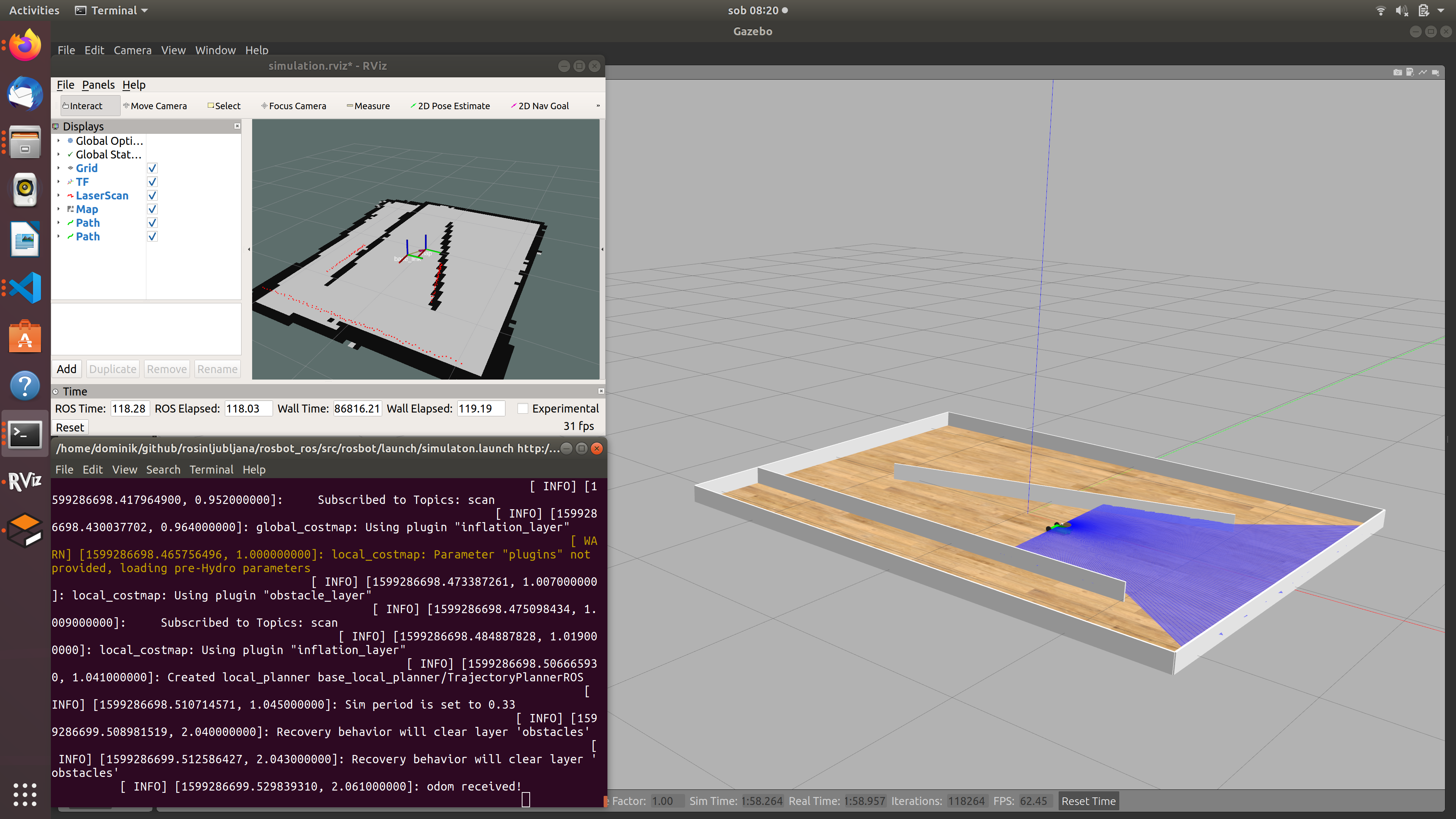
Launch the simuation
Run the launch file simulation.launch:
cd .../rosbot_ros/

catkin_make

source devel/setup.bash

roslaunch rosbot_simulation simulation.launch
Using the PC keyboard, you can now move the mobile robot around the polygon.
move_base node
The move_base node provides a more advanced way to control a mobile robot. The move_base node performs navigation tasks. Navigation is the ability of a mobile robot to determine its position in the environment where it is located (localization) and to plan and execute the path to a target location. It enables autonomous avoiding both static and dynamic obstacles.
The move_base node and all other components that are needed for this node to operate are already included in the .launch and other files presented above. Here in this last section of today's, tutorial it will be demonstrated how this node works.
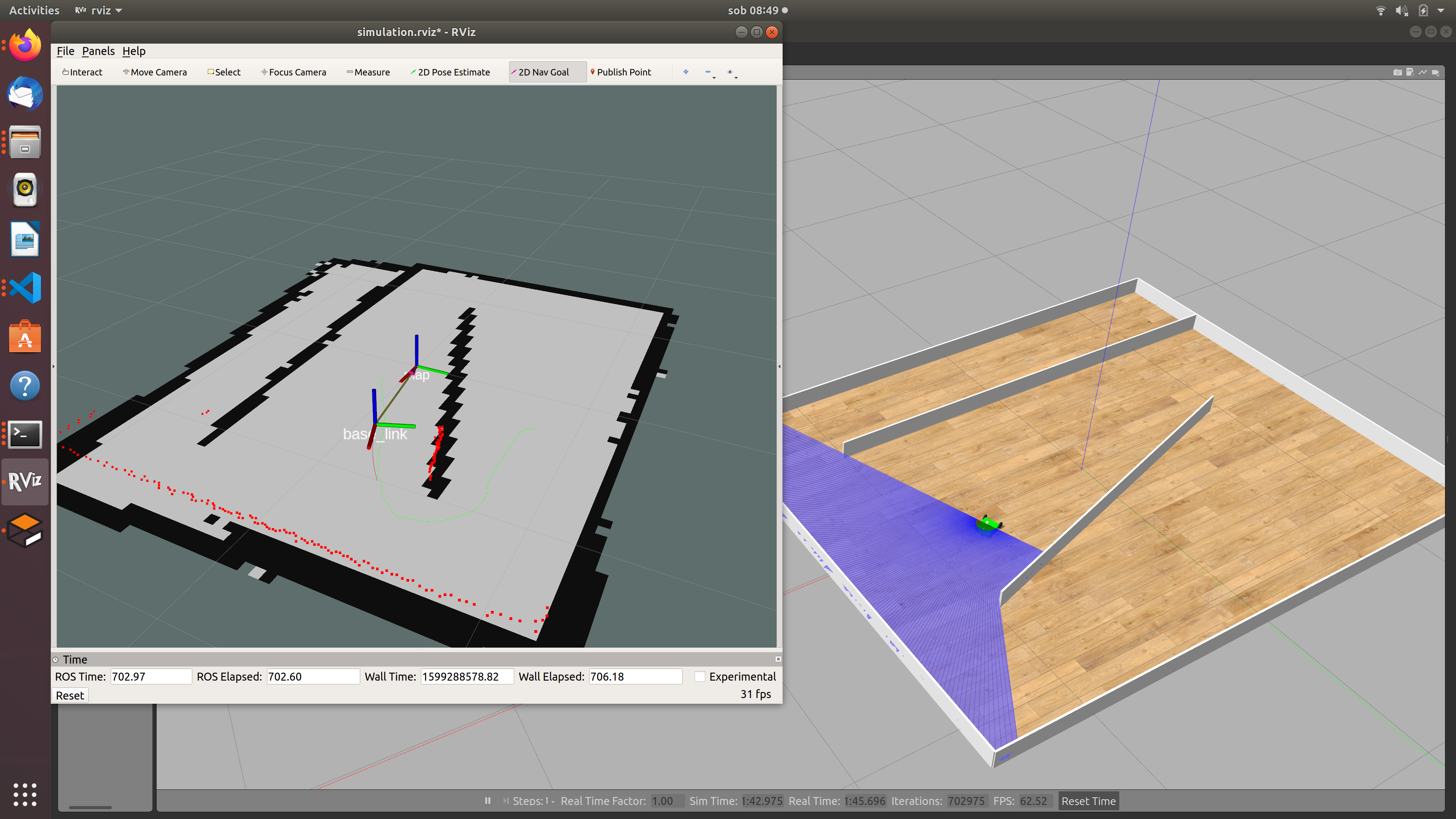
Task. Launch the simulation including RViZ as presented before. In the RViZ GUI, on the top of the window, you will find a (probably)pink arrow that can be used to specify a new target position and orientation of a mobile robot. Use this arrow and specify a target position and orientation. You should see, how a mobile robot starts planing the path to the target position and moving around the polygon towards the target position (calculating the path and autonomously moving towards the target position is enabled by the move_base node).
Additional taks
Create a new package trajectory_plan inside workospace rosbot_ros:
cd .../rosbot_ros/src
catkin_create_pkg trajectory_plan std_msgs roscpp
In this new package, create a new node that will be sending new goal positions to the move_base node in a way, that the robot will reach the locations below. The robot must first go to location 1, then to location 2, and finally to the location 3. Locations: (x1=-0.45, y1=0.7); (x2=1.35, y2=-0.75); (x3=-0.05, y3=-0.23).