Introduction
The mobile robot we are using at these tutorials has the following sensors:
- left wheel encoder
- right wheel encoder
- LiDAR
- IMU (gyro, accelerometer)
- Battery sensor
Encoders are used to enable PID control of the speed of the wheels and to calculate odometry. LiDAR is used for mapping the environment and navigation tasks. IMU can be used e.g. at improving the odometry.
The part of the mobile robot system where sensors measurements enter the ROS network is in the main.cpp file for a mobile robot (you can find that file in folder .../robot_core/src):
#include <Robot.h>

#include <WiFi.h>

#include <geometry_msgs/Twist.h>
#include <nav_msgs/Odometry.h>
#include <ros.h>
#include <sensor_msgs/BatteryState.h>
#include <sensor_msgs/Imu.h>
#include <sensor_msgs/LaserScan.h>
#include <std_msgs/Bool.h>
#include <std_msgs/Float32.h>
#include <std_msgs/Header.h>

ros::NodeHandle nh;
sensor_msgs::BatteryState battery_msg;
ros::Publisher battery_pub("battery", &battery_msg);
sensor_msgs::LaserScan laserscan_msg;
ros::Publisher laserscan_pub("scan", &laserscan_msg);
nav_msgs::Odometry odometry_msg;
ros::Publisher odometry_pub("odom", &odometry_msg);
sensor_msgs::Imu imu_msg;
ros::Publisher imu_pub("imu", &imu_msg);

...


void setup() {

    ...

    nh.initNode();
    nh.advertise(battery_pub);
    nh.advertise(laserscan_pub);
    nh.advertise(odometry_pub);
    nh.advertise(imu_pub);

    nh.subscribe(twist_sub);
    nh.subscribe(lidar_sub);

    ...

}

void loop() {

    ...
        ...
            ...

            if (!robot_moved)
            {
                laserscan_msg.header.stamp = nh.now();
                laserscan_pub.publish(&laserscan_msg);
            }
            else if (robot_moved && !robot.isMoving())
            {
                robot_moved = false;
            }
        }
    }

    if (current_time - update_time > 100)
    {
        update_time = current_time;

        battery_msg.header.stamp = nh.now();
        battery_msg.voltage = robot.battery.getVoltage();
        battery_pub.publish(&battery_msg);

        odometry_msg.header.stamp = nh.now();
        odometry_msg.pose.pose.position.x = robot.getPositionX();
        odometry_msg.pose.pose.position.y = robot.getPositionY();
        odometry_msg.pose.pose.position.z = 0.016;
        odometry_msg.pose.pose.orientation.w = cos(0.5 * robot.getRotation());
        odometry_msg.pose.pose.orientation.x = 0;
        odometry_msg.pose.pose.orientation.y = 0;
        odometry_msg.pose.pose.orientation.z = sin(0.5 * robot.getRotation());
        odometry_msg.twist.twist.linear.x = robot.getSpeedLinear();
        odometry_msg.twist.twist.angular.z = robot.getSpeedAngular();
        odometry_pub.publish(&odometry_msg);

        imu_msg.header.stamp = nh.now();
        imu_msg.angular_velocity.x = robot.imu.getGyroY() * PI / 180.0;
        imu_msg.angular_velocity.y = -robot.imu.getGyroX() * PI / 180.0;
        imu_msg.angular_velocity.z = robot.imu.getGyroZ() * PI / 180.0;
        imu_msg.linear_acceleration.x = -robot.imu.getAccY() * 9.81;
        imu_msg.linear_acceleration.y = robot.imu.getAccX() * 9.81;
        imu_msg.linear_acceleration.z = robot.imu.getAccZ() * 9.81;
        imu_pub.publish(&imu_msg);
    }

    nh.spinOnce();
}
The part of the program code above is to publish odometry, twist (linear and angular speed), laser scan, IMU, and battery state messages on ROS topics /odom, /cmd_vel, /scan, /imu, and /battery.
This part of the tutorials will present how we can access the data of these sensors in ROS and some examples of how the sensors data can be visualized.
Visualization of LiDAR measurements
Let us first look at how raw data from LiDAR look like when they are published on topic /scan. Just follow the steps below.
Switch ON the mobile robot and launch the mapping demo in a new terminal:
export ROS_IP=pc_ip_address

cd .../rosbot_ros/

source devel/setup.bash

roslaunch rosbot mapping.launch
Turn ON the LiDAR senzor:
rostopic pub /lidar std_msgs/Bool "data: true"
Alternatively, you can use rqt GUI to turn ON the LiDAR sensor.
Alternatively, if you e.g. don't have a real mobile robot, you can do these tasks also with a simulated one. To do this with a simulated robot, you need to launch the simulation:
cd .../rosbot_ros

source devel/setup.bash

roslaunch rosbot simulation.launch
Listen to the topic /scan:
rostopic echo /scan
Now you should be able to see in the terminal the data from the LiDAR sensor.
This data can be also visualized using a 3D visualization tool in ROS called RViZ.
Run RViZ by executing the following command in the new terminal:
rosrun rviz rviz
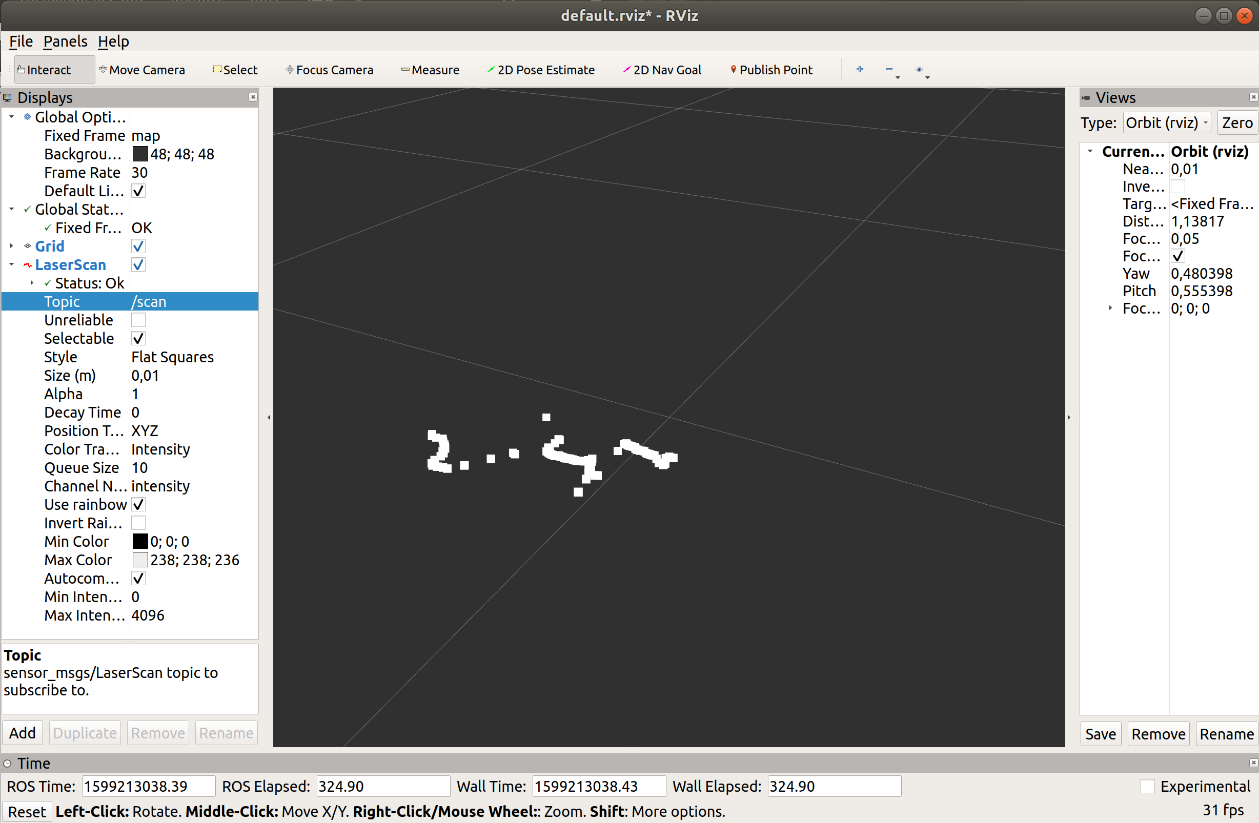
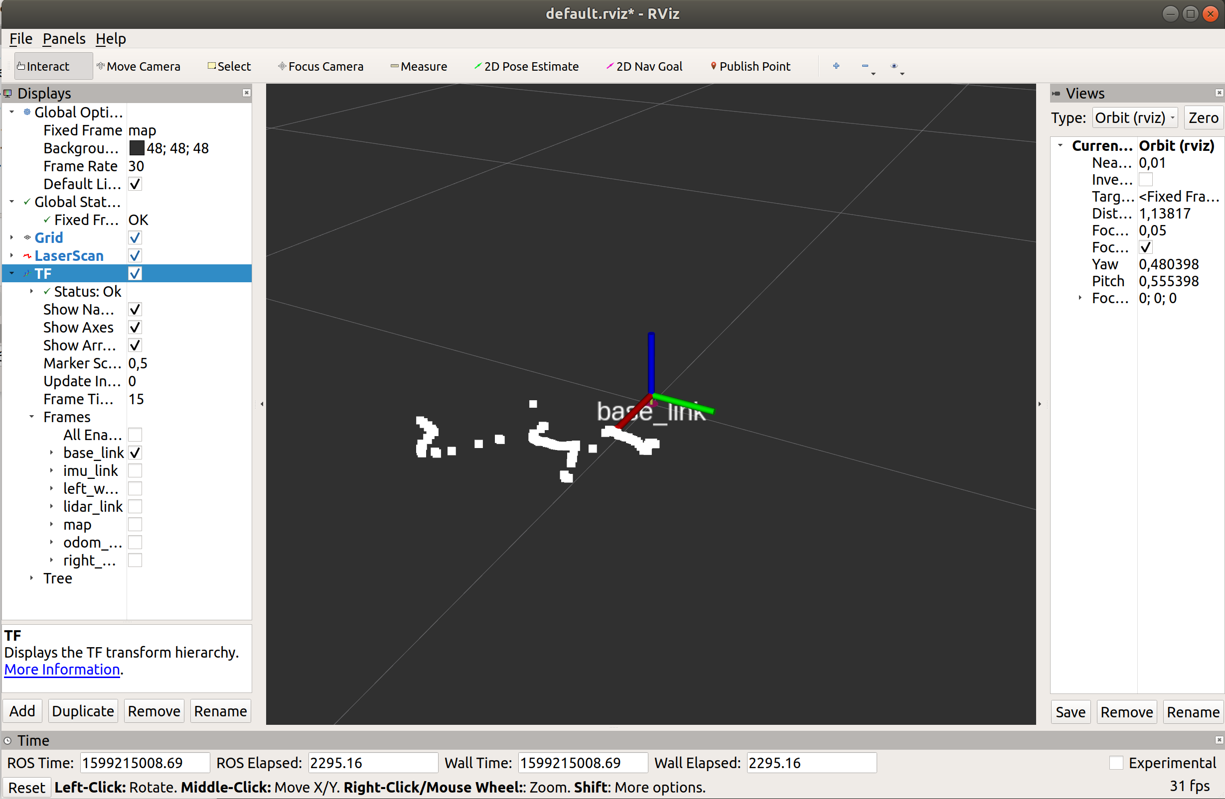
To add objects you want to visualize, click Add button located somewhere in the left bottom corner of the RViZ GUI and then select LaserScan object, and then set the topic of LaserScan object to /scan.
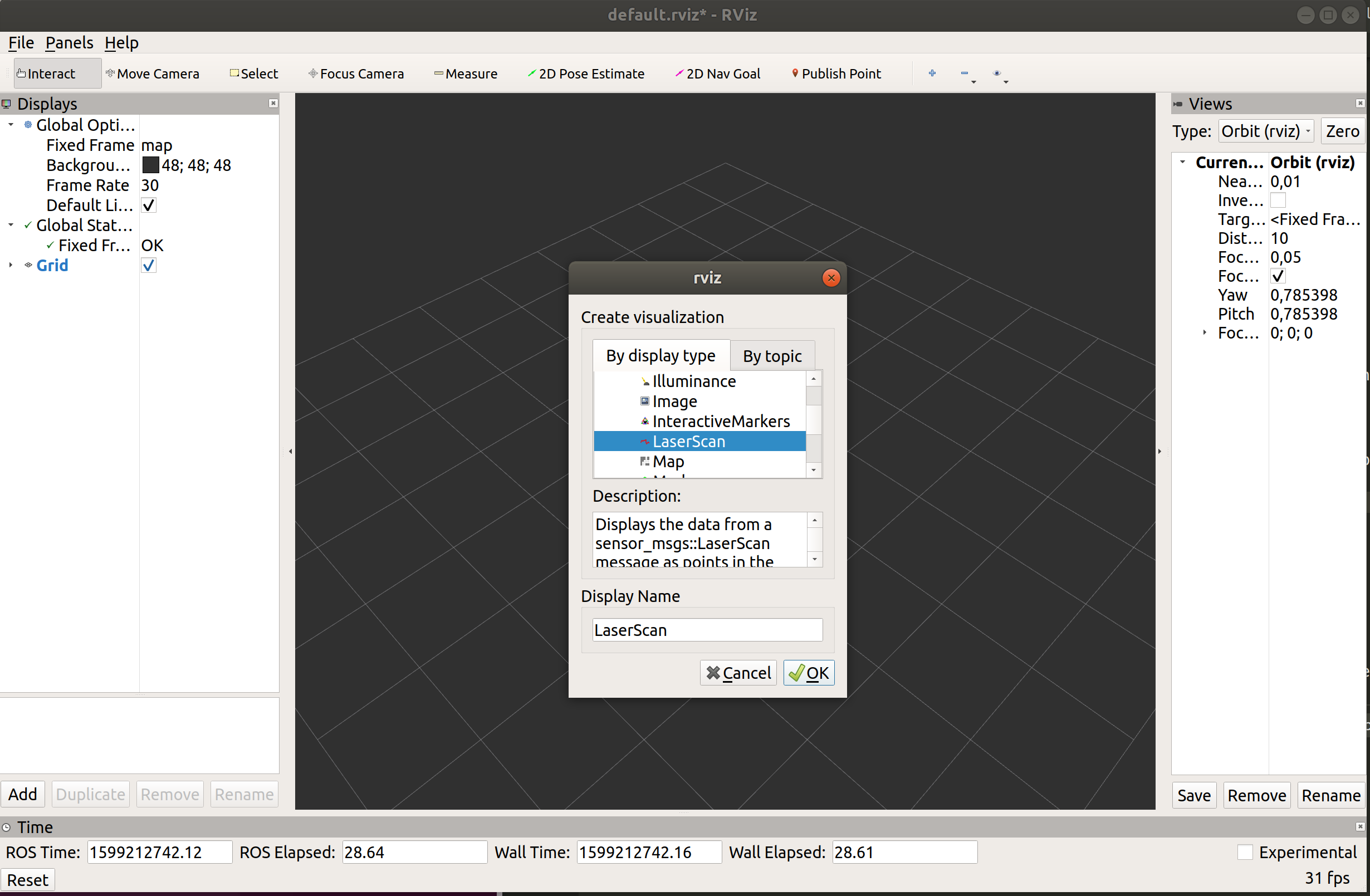
Now you should see the visualization of LiDAR sensor measurements in the RViZ GUI.
Optionally, you can add TF and using that object, add a visualization of a base_link frame (the center of the mobile robot base).
Mobile robot path visualization
The next thing it will be demonstrated here is how we can visualize a mobile robot trajectory based on sensor measurements.
The path is basically a sequence of locations visited by a mobile robot in the time until some moment. To figure out where a mobile robot is located, we can use odometry. There is already a tool in ROS that generates a robot trajectory based on odometry data, and this path can then be visualized in RViZ. Below is the procedure of how to install this tool (actually it is a server) named hector_trajectory_server, and then how to visualize the path of the mobile robot in RViZ.
Install hector_slam package:
sudo apt-get update

sudo apt-get install ros-melodic-hector-slam
If not yet, switch ON the mobile robot and launch the mapping demo in a new terminal:
export ROS_IP=pc_ip_address

cd ~/rosbot_ros/

source devel/setup.bash

roslaunch rosbot mapping.launch
Alternatively, if you e.g. don't have a real mobile robot, you can do these tasks also with a simulated one. To do this with a simulated robot, you need to launch the simulation:
cd .../rosbot_ros

source devel/setup.bash

roslaunch rosbot simulation.launch
Run the hector_trajectory_server:
rosrun hector_trajectory_server hector_trajectory_server _target_frame_name:="odom_delayed" _trajectory_pubish_rate:=4
! If you are using a simulated robot, you should run the trajectory server with a sligthly changed command:
rosrun hector_trajectory_server hector_trajectory_server _target_frame_name:="odom" _trajectory_pubish_rate:=4
Click on (bring forward) the RViz window which is already opened with the mapping demo.
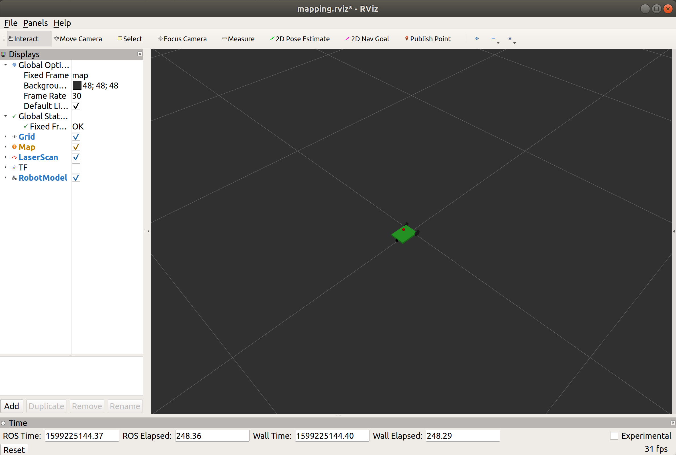
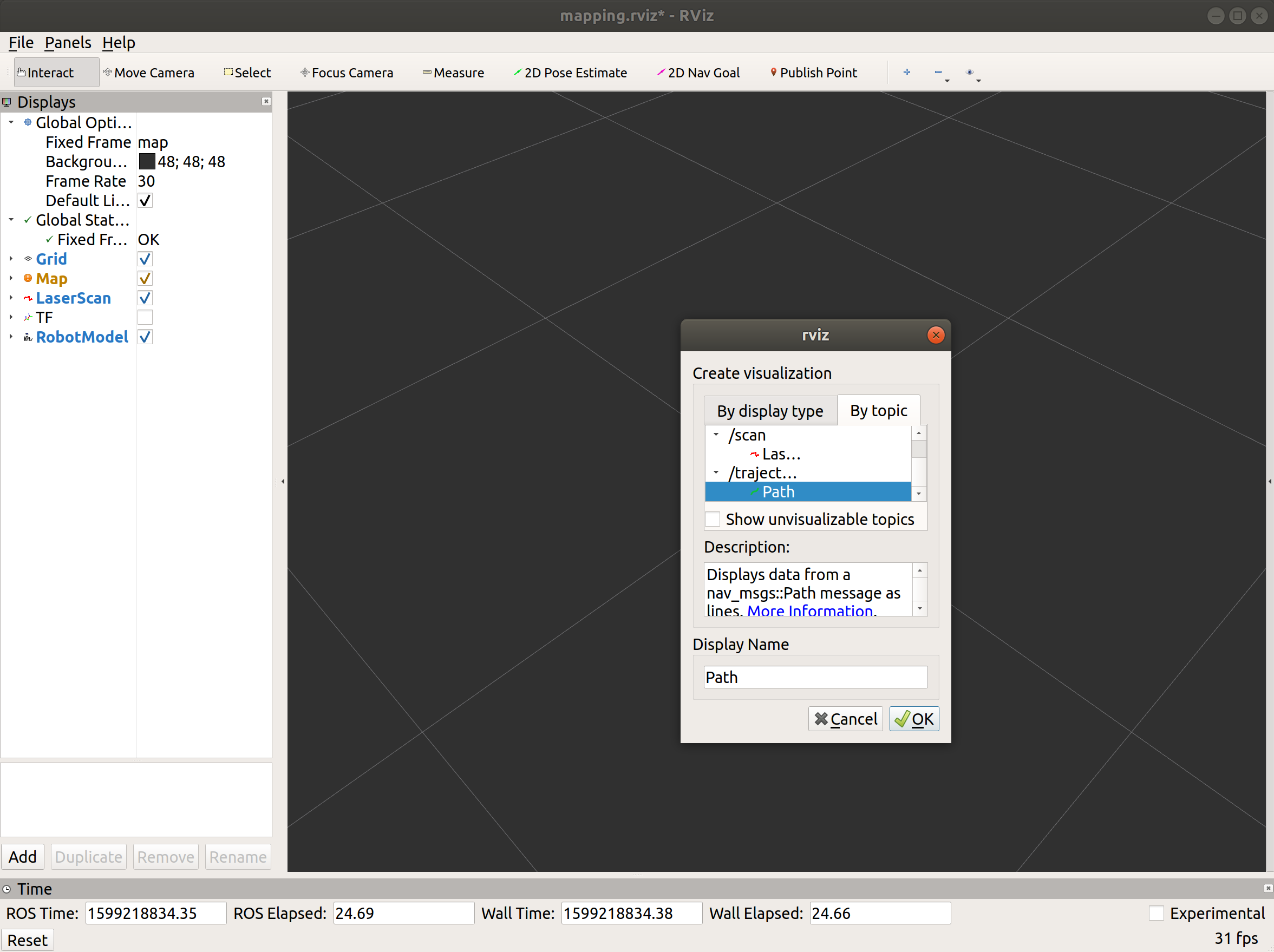
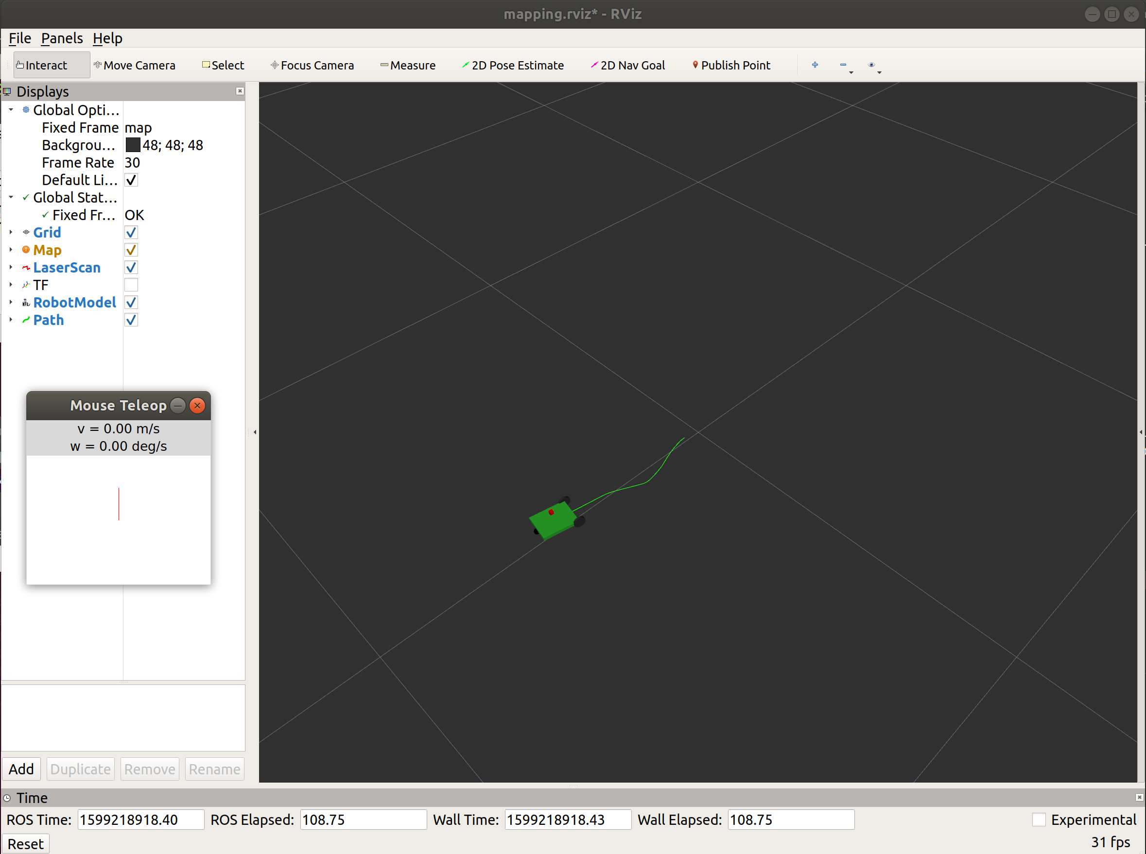
In a similar way to adding a laser scan to RViZ a few minutes ago, now add a path visualization (use /trajectory topic) and then use teleoperation to drive around the mobile robot.